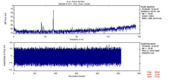
MOTOR CURRENT SIGNATURE ANALYSIS (MCSA):
With industrial growth, it has become necessary to monitor the condition of the machine/system. Electrical machines being the most sensitive part has great importance for the researcher to monitor the faults diagnosis. Three phase squirrel cage motor (Induction Motor) is normally used for industrial purposes. Various techniques are used to control the speed such as DTC (Direct Torque Control), Vector Control, Close Loop Feedback Control etc.
WHY WE USED MOTOR CURRENT SIGNATURE ANALYSIS (MCSA)
Motor Current Signature Analysis (MCSA) is a system used for analyzing or trending dynamic, energized systems. Proper analysis of MCSA results assists the technician in identifying:
1. Incoming winding health
2. Stator winding health
3. Rotor Health
4. Air gap static and dynamic eccentricity
5. Coupling health, including direct, belted and geared systems
6. Load issues
7. System load and efficiency
8. Bearing health
TOOL USED FOR MOTOR CURRENT SIGNATURE ANALYSIS (MCSA)
Tool that is used for testing MCSA EMERSON CSI 2130/2140 (with Complete Set of CT, PT, Flux Coil & Volt Adaptor)
ISO STANDARD
ISO 20958:2013 sets out guidelines for the online techniques recommended for the purposes of condition monitoring and diagnostics of machines, based on electrical signature analysis. ISO 20958:2013 is applicable to three-phase induction motors
POWER HARMONICS ANALYSIS
A harmonics analyzer is the most effective instrument for performing detailed analysis of power quality to determine the wave shapes of voltage and current on respective frequency spectrums.
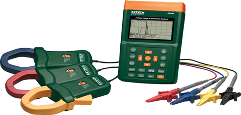
TESTING EQUIPMENT FOR POWER HARMONICS ANALYSIS
Equipment that we using for testing Power Harmonics Analysis EXTECH PQ-3350
FAULT DIAGNOSED
Many types of loads can cause harmonic currents, finding the culprit behind your power quality problem is anything but predictable. Adjustable speed drives, Electrical Panel and uninterruptible power systems are just a few of the devices that generate harmonic currents. However, their presence does not necessarily mean the phenomenon of harmonics exists. One of the most difficult things to determine in power quality analysis is whether a site is a prime candidate for harmonic problems. To help you in your troubleshooting efforts, let's look at the proper methods of measuring harmonic voltages and currents
1.Voltage and current measurements
Troubleshooting a power system for a suspected harmonics problem must include voltage and current measurements made with true RMS (root-means-square) digital meters. By using such a meter, you can accurately determine the voltage and current amplitudes in the presence of non-sinusoidal loads.
2.Voltage and current distortion.
To simplify your investigation, it helps to divide harmonic problems into two categories: voltage waveform distortion and current waveform distortion. Voltage distortion concerns electric utilities more than current distortion because it affects electrical delivery to the facility.
ISO STANDARD
IEEE standard 519-1992, Recommended Practice and Requirements for Harmonic Control in Electric Power Systems, states the total harmonic distortion (THD) of the voltage waveform provided by the utility cannot exceed 3% of the ideal sine wave. Make this measurement at the point of common coupling (PCC). This is where the utility and facility wiring meet (usually at the meter box). If the voltage distortion exceeds 3%, the utility should provide some form of mitigation to correct the problem.